
How we wired two NVIDIA DGX Spark workstations through a MikroTik CRS804-4DDQ switch, discovered four hardware ceilings, and ended up moving 340 Gbit/s full-duplex between GPUs with the CPU sitting at idle.
The setup
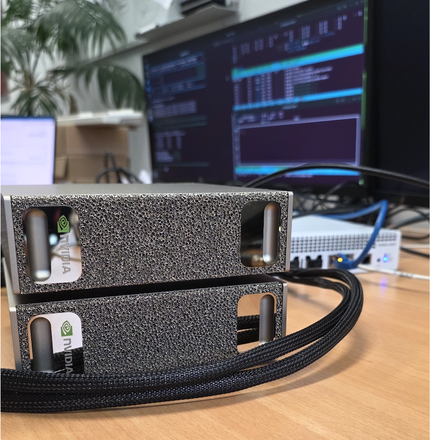
Two NVIDIA DGX Spark workstations sitting next to each other in the lab, each with an NVIDIA GB10 superchip (Grace ARM CPU + Blackwell GPU, unified LPDDR5X memory). Each Spark has two 200 GbE QSFP56 ports on a ConnectX-7 SmartNIC for clustering, plus a 10 GbE RJ45 for management.
Sitting between them: a MikroTik CRS804-4DDQ — a four-port 400 G QSFP-DD switch built on a Marvell 98DX7335 ASIC. Each physical port can carry a single 400 G connection or be split into 2× 200 G or 4× 100 G. RouterOS 7.22.
The question was simple: what’s the best inter-node bandwidth we can actually get?
The answer turned out to be layered, because TCP, RDMA, and the silicon all have different ceilings.
Special thanks to Wireless Professional Solutions to supply NVIDIA DGX Spark hardware — see specs, pricing, and availability: Link
Stage 1 — Just plug it in and ping
Two 200 G DACs, one from each DGX, into the same physical QSFP-DD port on the switch using a 2× 200 G breakout. Both DGXes get DHCP addresses on 192.168.88.0/24 from RouterOS. Management interface on the laptop comes up on the same subnet. Pings work. Done.
This was the easy part. Then we ran our first benchmark.
iperf3 -c <peer> -P 16 -t 20Result: 96.2 Gbit/s. Half of the 200 G line rate. The expected number on an untuned setup.
Stage 2 — Why is the TCP number so low?
At 200 Gbit/s, the CPU spends most of its budget on packets per second, not bytes. With the default Ethernet MTU of 1500, every gigabit of throughput costs around 80,000 packet headers, copies, and interrupt entries. On a Grace CPU this caps out fast.
Three knobs needed turning:
- MTU 9000 (jumbo frames) on every hop — host NICs and the switch ports.
- TCP socket buffers large enough to accommodate the bandwidth-delay product (200 Gbit/s × 1 ms RTT ≈ 25 MB per stream).
- NIC offloads (TSO, GSO, GRO) on, which they already were.
MikroTik side turned out to be more involved than just set mtu=9000. RouterOS 7 clamps MTU to the configured L2MTU, and the L2MTU on a 200 G port was sitting at 1584 by default. The working ports on the same switch had explicit overrides for everything — auto-negotiation off, speed forced to 200G-baseCR4, FEC mode fec91. We replicated that config on the new ports:
/interface/ethernet/set qsfp56-dd-2-1 \
    auto-negotiation=no \
    speed=200G-baseCR4 \
    fec-mode=fec91 \
    l2mtu=9216 mtu=9000
Host side got a sysctl bump:
sysctl -w net.core.rmem_max=536870912
sysctl -w net.core.wmem_max=536870912
sysctl -w net.ipv4.tcp_rmem="4096 87380 134217728"
sysctl -w net.ipv4.tcp_wmem="4096 65536 134217728"
sysctl -w net.core.netdev_max_backlog=300000
ip link set <iface> mtu 9000
End-to-end verification with ping -M do -s 8972 — full-size jumbo, don’t-fragment flag set — went through cleanly with sub-millisecond RTT.
We re-ran iperf3 with the same -P 16 and got… 98 Gbit/s.
Tuning helped exactly 2%. Something else was the bottleneck.
Stage 3 — Discovering the multi-host architecture
Each DGX Spark reported two active 200 G interfaces (enp1s0f0np0 and enP2p1s0f0np0), both at 200 Gbit/s, both with separate MAC addresses. The switch FDB confirmed both MACs appeared on the same switch sub-port:
4C:BB:47:83:75:FD  qsfp56-dd-1-5
4C:BB:47:83:76:01  qsfp56-dd-1-5    ← same port!
So the DGX Spark presents its single physical 200 G port as two logical PCIe interfaces with different MACs. This is ConnectX-7’s “Multi-Host” feature — the same NIC silicon is accessible via two PCIe paths (PCIe domains 0000:01 and 0002:01), and each path gets a fraction of the bandwidth.
Empirically we confirmed each logical interface caps at roughly 100 Gbit/s of TCP throughput. The two halves of the 200 G physical pipe are usable independently:
| Test | Throughput |
|---|---|
| Single TCP stream, single logical NIC | 21 Gbit/s |
| 16-stream TCP, single logical NIC | 98 Gbit/s |
| 16-stream TCP, both logical NICs in parallel | 177 Gbit/s |
RDMA ib_send_bw -q 8, single logical NIC | 99 Gbit/s |
That parallel-NIC number — 177 Gbit/s — is 88% of the 200 G physical wire on a single cable, which is what production-tuned 200 GbE TCP looks like on a Grace CPU. Good. But we were still leaving 23 Gbit/s on the table, and there was nothing left to tune host-side without going to RDMA.
Stage 4 — Adding a second cable
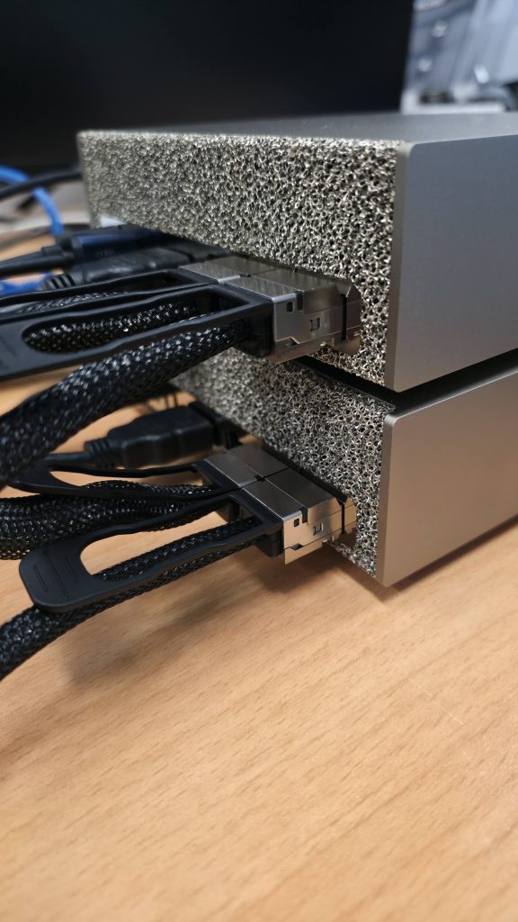
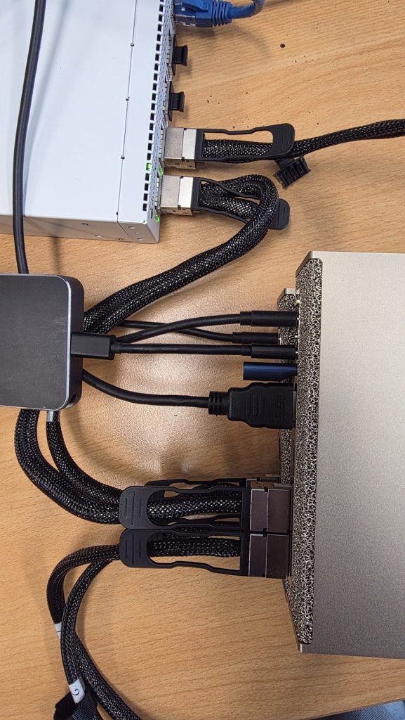
The plan was to plug a second cable from each DGX into the switch’s free 400 G ports and see whether we could hit 400 Gbit/s aggregate. Each DGX has two physical 200 G ports total; only one was wired up. Plug the other one in, configure the new switch ports to match the working ones, and you’ve doubled the available wire bandwidth.
After plugging, the switch saw new transceivers but no link. Same problem as before: the new ports had RouterOS defaults (auto-neg yes, FEC auto), and the ConnectX-7 DACs need the manual overrides. After applying the same config:
status=link-ok    qsfp56-dd-2-1
status=link-ok    qsfp56-dd-2-5
Both new cables came up at 200 G. Total wire capacity now 400 Gbit/s per DGX, 800 Gbit/s aggregate full-duplex on the cluster.
Then we re-ran the TCP test with four parallel iperf3 streams, one per logical NIC, each pinned to disjoint CPU sets:
| Streams | Aggregate TCP |
|---|---|
| 2 (single cable, both logical NICs) | 177 Gbit/s |
| 4 (both cables, all four logical NICs) | 171 Gbit/s |
Adding the second cable made TCP slightly worse. Each stream got a smaller slice of CPU; the cables themselves never came close to saturating.
The Grace CPU’s TCP stack tops out around 170–180 Gbit/s of aggregate throughput, regardless of how many physical cables are available. That’s the kernel TCP ceiling, not a network ceiling.
To go past it we had to get rid of TCP entirely.
Stage 5 — NCCL and RDMA: the real measurement
The “right” way to measure inter-node bandwidth on a DGX is the way DGX clusters actually communicate: NCCL (NVIDIA Collective Communications Library) running over RoCEv2 (RDMA over Converged Ethernet). This is the protocol stack NCCL uses for multi-GPU all-reduce, all-gather, sendrecv, etc. — every multi-node ML training job in the world is built on it.
Setup on both DGXes:
sudo apt install -y libnccl2 libnccl-dev libopenmpi-dev openmpi-bin
git clone https://github.com/NVIDIA/nccl-tests
cd nccl-tests && make -j8 MPI=1 \
    CUDA_HOME=/usr/local/cuda \
    MPI_HOME=/usr/lib/aarch64-linux-gnu/openmpi \
    NCCL_HOME=/usr
Plus passwordless SSH between the two hosts (mpirun’s launch agent), and the four RoCE devices listed explicitly:
mpirun -np 2 -H 192.168.88.248:1,192.168.88.252:1 \
    --mca plm_rsh_agent ssh \
    -x NCCL_IB_HCA=rocep1s0f0,rocep1s0f1,roceP2p1s0f0,roceP2p1s0f1 \
    -x LD_LIBRARY_PATH=/usr/local/cuda/lib64:/usr/lib/aarch64-linux-gnu \
    ./build/sendrecv_perf -b 256M -e 4G -f 2 -g 1 -n 30 -w 5
Result at 4 GB messages:
#       size         busbw (GB/s)
   268435456            20.14
   536870912            20.26
  1073741824            20.28
  2147483648            20.25
  4294967296            20.38
20.38 GB/s busbw. In NCCL’s accounting for a 2-rank sendrecv, that means 163 Gbit/s of data crossing the network in each direction simultaneously. Full-duplex aggregate: 326 Gbit/s.
Live PHY-layer counters (read straight from the ConnectX-7 silicon via ethtool -S | grep _bytes_phy) confirmed it: ~84 Gbit/s TX + ~84 Gbit/s RX on each of the two cables, peaking at 340 Gbit/s of bytes physically moving across the wire.
The CPU was idle the entire time.
Why CPU is idle while 340 Gbit/s flies through the box
This is the whole point of RDMA, and it’s worth understanding because it explains why you can’t iperf your way to honest DGX-class bandwidth numbers.
TCP path (what iperf3 measures):
GPU memory → copy to CPU buffer → kernel TCP stack → syscall →
driver → NIC → wire
Every byte traverses the kernel. Header processing, checksums, segmentation, retransmit queues, copy_from_user — all of it eats CPU cycles. At 200 Gbit/s the CPU is fully consumed packetizing.
RDMA path (what NCCL uses):
GPU memory ──PCIe DMA──→ NIC ──wire──→ NIC ──PCIe DMA──→ GPU memoryNCCL posts a single work-queue entry into the ConnectX-7’s hardware: “read 4 GB from address X, deliver to remote address Y.” The NIC’s DMA engine fetches the data straight out of memory, packetizes in silicon, pushes to the wire, and signals completion via an interrupt. The kernel doesn’t see the bytes. No copies. No syscalls per packet.
On a DGX Spark this is even more elegant than on a discrete-GPU system, because the GB10 has unified LPDDR5X memory — the GPU and CPU share the same physical RAM. So “GPU memory” is just an address range, and the NIC DMAs straight into and out of the unified pool. There’s no PCIe-CPU-PCIe-GPU bounce buffer.
What the GPU is “doing” during the test isn’t compute — it’s orchestration. NCCL runs tiny CUDA kernels that build the RDMA work requests and poll completion queues. The actual data movement is silicon.
The CPU’s contribution is microseconds of work to post the initial work request. After that, it goes idle until the NIC raises a completion interrupt some seconds later.
Final results
Same hardware, same cables, three protocols:
| Protocol | Per-direction | Full-duplex aggregate | CPU usage | What’s limiting |
|---|---|---|---|---|
| TCP — single stream | 21 Gbit/s | 42 Gbit/s | One core saturated | Single-stream TCP window/CPU |
| TCP — 16 parallel streams, 1 cable | 98 Gbit/s | 196 Gbit/s | Heavy | iperf3 single-thread data path |
| TCP — 2 logical NICs parallel, 1 cable | 177 Gbit/s | 354 Gbit/s | Heavy | Grace CPU TCP stack |
| TCP — 4 logical NICs, 2 cables | 172 Gbit/s | 344 Gbit/s | Heavy | Same — adding cables doesn’t help |
| NCCL/RDMA — 2 cables | 163 Gbit/s | 326 Gbit/s | Idle | Approaching wire speed |
| PHY-layer observed peak | — | 340 Gbit/s | Idle | The cables themselves |
A few takeaways:
- TCP is the wrong measurement tool above ~150 Gbit/s on ARM. The Grace CPU’s TCP stack tops out around 170-180 Gbit/s regardless of how many cables you have. This isn’t a tuning issue — it’s the cost of running TCP through the kernel.
- Adding cables doesn’t help TCP. Going from one cable to two doubled wire capacity but TCP throughput stayed flat. The bottleneck moved from the wire to the kernel, and you can’t tune past it.
- NCCL/RDMA delivers what the silicon promises. 326 Gbit/s aggregate is 82% of the 400 G total per-direction capacity across two cables, and the CPU is asleep. That’s the protocol DGX clusters were built for.
- The second cable doubles redundancy and full-duplex capacity, not single-direction throughput. Each cable is 200 G in each direction (400 G full-duplex per cable). The pair gives 800 G full-duplex of theoretical capacity. NCCL was using about 40% of that with default settings. There’s almost certainly more available with PFC tuning for RoCEv2 lossless mode, GDR enabling, and channel/QP increases.
- ConnectX-7 Multi-Host is a real architectural choice. Each 200 G physical port presents as two ~100 G logical interfaces to the OS. This is great for parallelism but means single-flow apps see half the wire.
Reproducing this
If you’ve got two ConnectX-7-equipped machines and a CRS804-4DDQ (or any 400 G switch), the recipe:
Switch: match working port config exactly. Auto-neg off, speed forced, FEC explicit, L2MTU large enough for jumbo:
/interface/ethernet/set <port> \
    auto-negotiation=no speed=200G-baseCR4 fec-mode=fec91 \
    l2mtu=9216 mtu=9000
Host: sysctls and MTU:
sudo ip link set <iface> mtu 9000
sudo sysctl -w net.core.{r,w}mem_max=536870912 \
    net.ipv4.tcp_rmem="4096 87380 134217728" \
    net.ipv4.tcp_wmem="4096 65536 134217728" \
    net.core.netdev_max_backlog=300000
For multi-IP same-subnet on multiple interfaces:
sudo sysctl -w \
    net.ipv4.conf.all.arp_ignore=1 \
    net.ipv4.conf.all.arp_announce=2 \
    net.ipv4.conf.all.rp_filter=2
Benchmark: NCCL is the canonical measurement. Build nccl-tests, set up passwordless SSH between hosts, and:
mpirun -np 2 -H host1:1,host2:1 \
    -x NCCL_IB_HCA=<list of RoCE devices> \
    ./build/sendrecv_perf -b 256M -e 4G -f 2 -g 1 -n 30 -w 5
The reported busbw × 8 is your per-direction wire bandwidth in Gbit/s.
The live view
We also built a small Python tool that runs the NCCL benchmark and renders live PHY-layer throughput bars next to it. It reads tx_bytes_phy and rx_bytes_phy from ethtool -S (those are the only counters that see RDMA bytes — kernel /sys/class/net/<iface>/statistics/tx_bytes misses everything that doesn’t touch the IP stack).
The display shows TX/RX bars per cable filling from gray to cyan as the test ramps from 256 MB messages up to 4 GB, with a running NOW/PEAK aggregate at the bottom. Peak observed in our runs: 340 Gbit/s full-duplex while the CPU sat at single-digit utilization.
╔══════════════════════════════════════════════════════════════════════════════════════╗
║   DGX Spark Pair — Live Inter-Node Bandwidth   (NCCL sendrecv · RoCEv2 RDMA)         ║
║   Node A ⇄ CRS804-4DDQ ⇄ Node B   |   2× 200G ConnectX-7 cables                      ║
╠══════════════════════════════════════════════════════════════════════════════════════╣
║  Cable 1  (200G)   TX ██████████████████████░░░░░░░░░░░░░░░░  82.4 Gb/s              ║
║                    RX ██████████████████████░░░░░░░░░░░░░░░░  85.6 Gb/s              ║
║  Cable 2  (200G)   TX ██████████████████████░░░░░░░░░░░░░░░░  83.1 Gb/s              ║
║                    RX ██████████████████████░░░░░░░░░░░░░░░░  84.8 Gb/s              ║
╠══════════════════════════════════════════════════════════════════════════════════════╣
║   NOW      TX  165.5 Gb/s  RX  170.4 Gb/s  Full-duplex  335.9 Gb/s                   ║
║   PEAK     TX  168.0 Gb/s  RX  171.2 Gb/s  Full-duplex  338.8 Gb/s                   ║
╚══════════════════════════════════════════════════════════════════════════════════════╝
What’s next
There’s more to extract. Things on the list:
- PFC + ECN for lossless RoCEv2. RouterOS supports priority flow control. With lossless transport NCCL can push closer to line rate without ECN-driven backoff.
- GDR (GPUDirect RDMA) wiring. Current runs report
GDR 0— the GPU is using a host-side staging step. Enabling true GDR (where the NIC reads directly from GPU memory regions without unified-memory indirection) should help on workloads with non-contiguous tensor layouts. - NCCL_NCHANNELS_PER_NET_PEER tuning. We set this to 4 explicitly; sweeping it may show a sweet spot.
- Higher rank counts. Two ranks is the simplest test. Three+ ranks would test ring vs tree algorithm choices and reveal collective scaling.
ib_write_bwwith proper QP fanout. As a sanity check against NCCL, raw RDMA write benchmarks should hit similar or slightly higher numbers.
For our purposes — measuring what two DGX Sparks can actually deliver between each other over a small switch — 326 Gbit/s of useful workload bandwidth, scaling linearly with two cables, with the CPU idle, is what the platform is designed to do. That’s the number worth quoting.
The platform delivers exactly what NVIDIA says it does, as long as you measure it with the right protocol.
Get this set up — or build any AI project — with us
The journey above touched every layer of the stack: RouterOS sub-port configuration, ConnectX-7 multi-host quirks, kernel TCP tuning, RoCEv2 setup, NCCL parameter selection, persistent configuration, benchmark methodology. None of it is rocket science. All of it is fiddly enough to silently cap your cluster at half its capability if you skip a step.
We help teams across the full spectrum of AI work — infrastructure setup, RDMA tuning, NCCL benchmarking, cluster commissioning, model deployment and serving, fine-tuning, retrieval pipelines, and custom AI integrations end-to-end. If you’re standing up DGX hardware, scoping an AI project, or want a sanity check on something already in flight, we’d be glad to help.
Reach us: info@catharsis.net.au